Converting a bally 7 digit display to a led display
A fellow pinball collector (Arno Baumfalk) in germany designed a new display pcb for the bally pinballs. This pcb uses 7 segment leds. Here is his homepage .
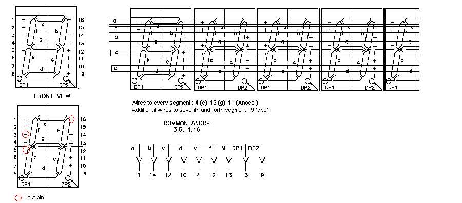
Here you see a part of his schematics:
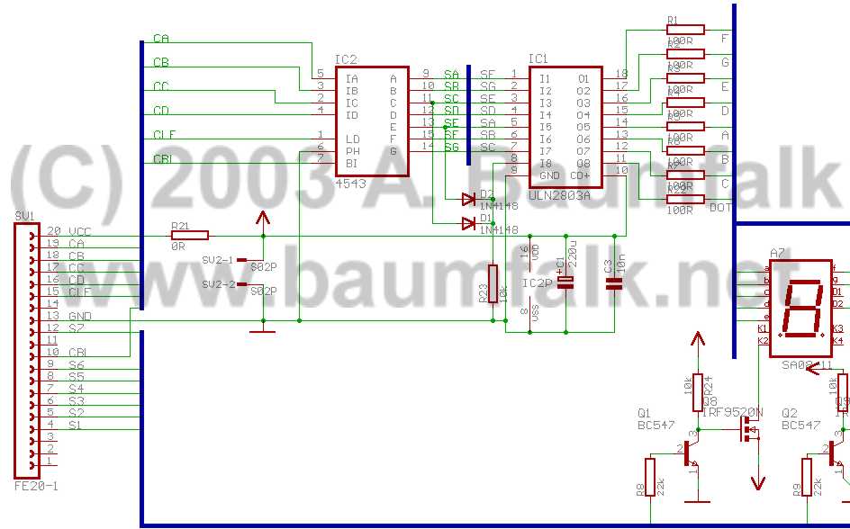
We need the following hardware for converting an old bally display pcb:
7 * segment SA08-11YWA  20 mm yellow  common anode
1 * ULN2803A
7 * 2n3904
7 * IRF9520N
1 * (elko) cap 220uf
some resistors....
and of course an old 7 digit display pcb...
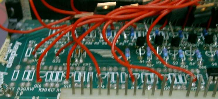
First I removed all components from the display board except :
4543
resistors r49 - r54
Cr1, cr2
C1
IMPORTANT REMOVE PIN 1 FROM THE MOLEX CONNECTOR , THE HIGH VOLTAGE IS NOT LONGER USED !!!
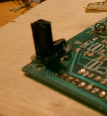
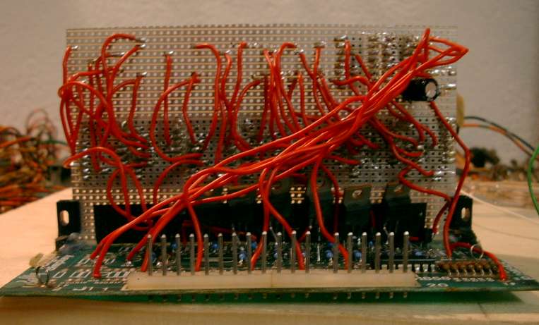
I found small plastic angles in a local electronic shop to hold the additional pcb in place. This additional pcb will hold the 7 * SA08-11, the ULN2803 and some resistors.
I used super glue to attach these angles to the old pcb.
Mount resistors 22k at the following locations:
r48,r47,r46,r45,r44,r43,r55
Mount resistors 10k at the following locations:
r2,r4,r6,r8,r10,r12,r57,r63
Mount resistor 0r (bridge) at the following locations:
r1,r3,r5,r7,r9,r11,r56
Mount 2n3904 at the following locations:
Q1,Q2,Q3,Q4,Q5,Q6,Q20
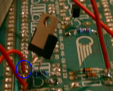
Mount IRF9520 at the following locations:
Q7,Q8,Q9,Q10,Q11,Q12,Q21
Attention: Look at the orientation of the legs (IRF9520):
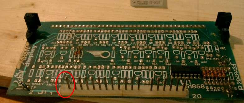
Connect every SA08-11 (pin 11, anode) to the following locations:
SA08-11 position on new pcb    resistor number (blue circle, take the hole close to the angles)
1 digit                        r35
2                              r36
3                              r37
4                              r38
5                              r39
6                              r40
7 digit                        r58
Connect Tp1 to location VR1 (take the hole close to the angles) with a wire. (TP2 now also have 5 V)
Connect wires to the base (green circle) of the following locations:

Segment location on pcb   connect to ULN2803 pin
a       B - Q13           5
b       B - Q14           6
c       B - Q15           7
d       B - Q16           4
e       B - Q17           3
f       B - Q18           1
g       B - Q19           2
dp      B - Q22           8
For the prototype I used too many wires for segment control on the additional pcb. I think, If you cut the not used SA08-11 pins (3,5,16), you only need three wires for one segement. I will test this for my next pcb.
Mount the ULN2803 and 8 * 100r resistor on the additional pcb.
segment ULN2803 pin       resistor            SA08-11 pin
a       14                100r                1
b       13                100r                14
c       12                100r                12
d       15                100r                10
e       16                100r                4 (separate wires for every segment required)
f       18                100r                2
g       17                100r                13 (separte wires for every segment required)
dp      11                100r                9 (connect only segment 7 and 4)
Connect the ULN2803 pin 9 to the ground (you can use the location r42) and the ULN2803 pin 10 to + 5V (use location c2, take the hole close to the angles). Connect the large cap between pin 9 and pin 10 from the uln2803.
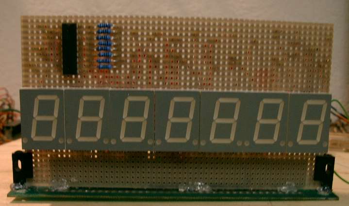
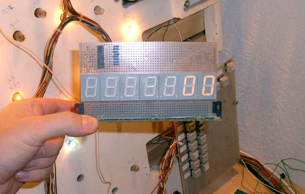
Here you see the additional pcb with the 7 * SA08-11, the ULN2803, 8 * 100r resistors and the cap. I don't use a socket for the ULN2803 (because then the chip would be to close to the backglass).
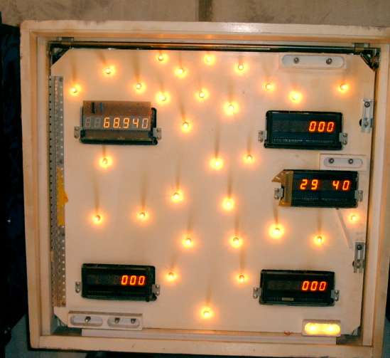
Testing on my testbench....
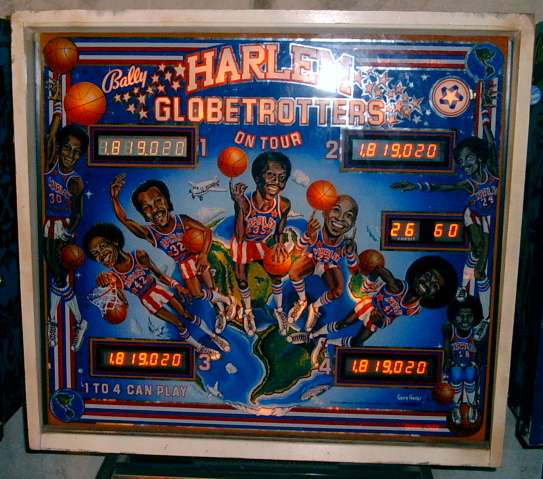
Here you see my harlem globetrotter:
Let us play...
Some "last words..:"
Modification is done at your own risk !!
Do it only with nonworking (outgased) display pcbs !!
IMPORTANT REMOVE PIN 1 FROM THE MOLEX CONNECTOR , THE HIGH VOLTAGE IS NOT LONGER USED !!!
(If you don't do this you will blow up the 5 Volt circuit with high voltage, killing everything in your pinball !!)
Mail me