After repairing some bally pcbs I decided to build a testplace.
I used the following material:
A complete wire harness (Bally)
A complete power supply (Bally)
A speaker
A lot push buttons, and diodes
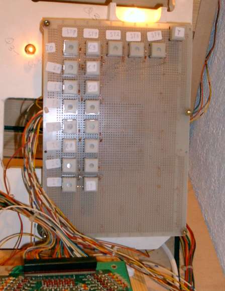
A complete lamp holder from the backbox (Bally)
I mounted the wire harness on a large piece of wood.
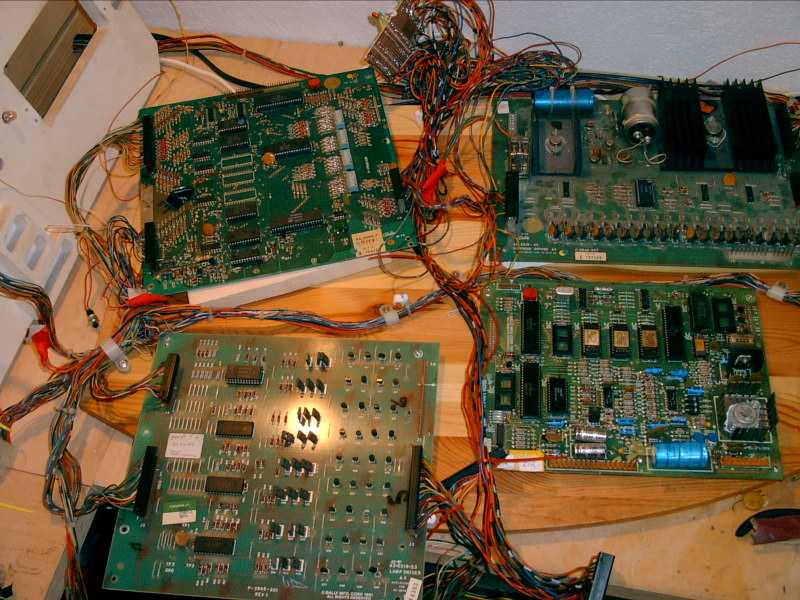
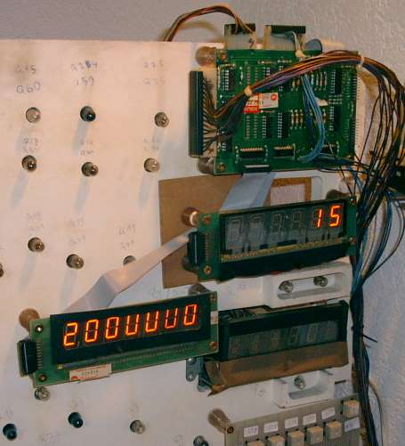
Then I connected the wires from the lamp driver connecters (J1,J2 and J3) to the lamps.The connector J3 and J1 are attached to the same lamps. Then I wrote down the SCR name (Q..) on the lamp holder.
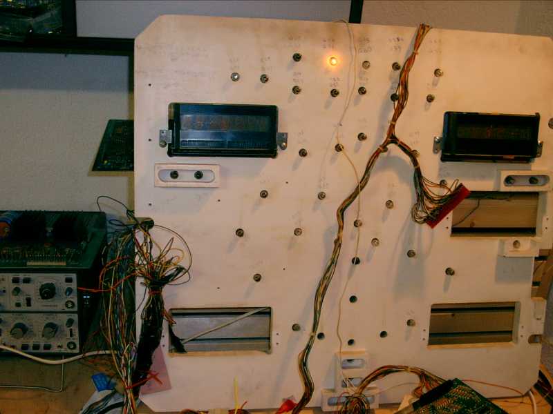
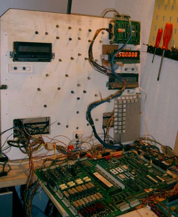
With this configuration I can test a lamp board very quickly. The power supply and the loud speaker are behind the lamp holder.
For the solenoid driver I attached the connectors to leds with resistors.
Update (18.5.2003):
I replaced the single pushbutton with a pcb:
I mounted the pushbuttons on a pcb. Then I connected the Strobe and the Input lines (j2) and the self test line (j3, pin 1). Now I can play pinball on my workbench !!!
Update (24.5.2003):
I mounted a little switch to switch between 7 digit and 6 digit game roms:
Switchschema:
GND ---------------- A8j1-12 (Soundconnector) ----+
A1J1-12 (Display)--- A4j1-7 (Mpuconnector) -------+
For the 7 digit games the gnd is connected to A8J1-12.
The A1j1-12 is connected to the a4j1-7.
For the 6 digit games the a8j1-12 is connected to the A4j1-7.
With this testplace I can test the following boards (using the normal self testroutine):
MPU
Lamp drivers (including auxilary...)
Solenoid Boards (including high voltage section)
Old Sound cards (Typ AS 2518-32) from Star Trek or Harlem (the work with the S&T sound connectors...)
Computer Sound Module Typ AS (2518-51) from frontier and Hotdoggin
S&T Boards (Typ 2518-61)
6 and 7 digit displays
Just added a connector for the centaur say-it-again board....
(Xenon sound card, not sure, I must check the connector of the sound card)
Maybe I'm exaggerating my hobby a little bit, but it is much easier to repair pcbs with this configuration.
Williams part
Update (18.10.2003)
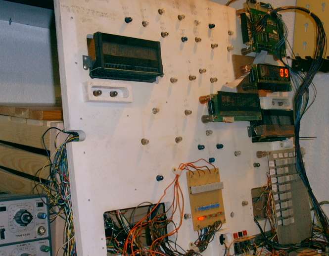
I decided to add williams support (system 3 - 7).
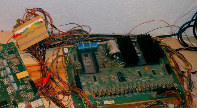
I used a system 6 power board and mount it on a piece of wood.
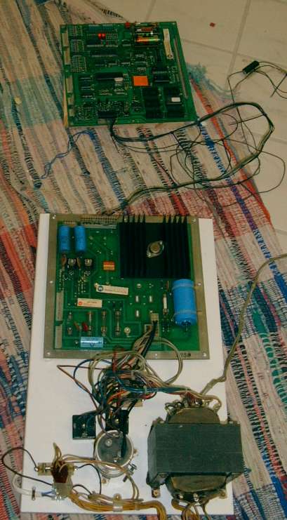
Above you see a system 6 board with leons test rom (I helped him to improve his memory test a little)...
The willimas powerboard is behind the lamp holder. I rearanged the things on the lamp holder to free up some space.
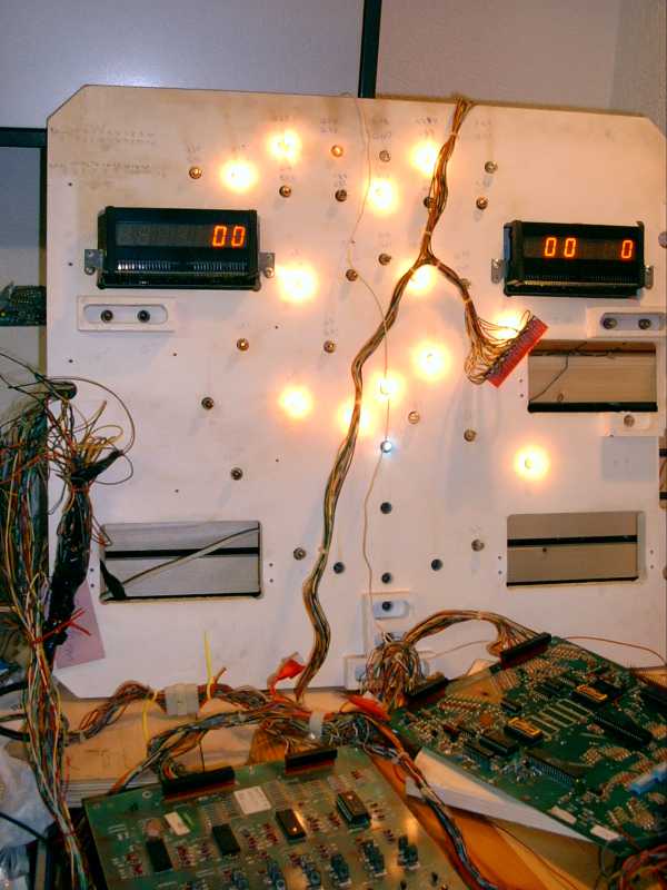
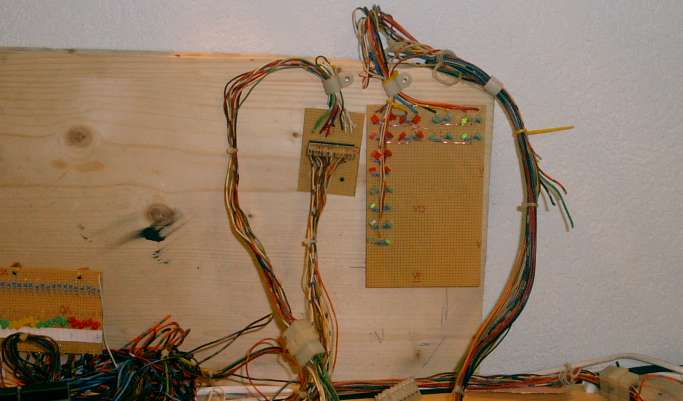
For the lamp matrix I built a little pcb with leds. Before every led I put a 750 Ohm resistor. Here you see the attract modus of a black knight...
First I thought I could work with my testplace with only one 7 digit display. But Williams displays the switch and the solenoid number in the two rightmost digits of the credit display.
So I modified a 6 digit display glass. Look here for details.
I built a little pcb with leds for the solenoids. Before every led I put a 1.2 Kohm resistor. With the six additional switches above the leds you can trigger the special solenoids.
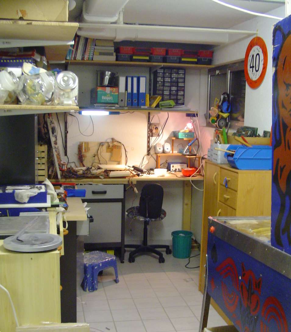
After a hard working weekend I moved my testplace to a new corner in my gameroom.
Mail me